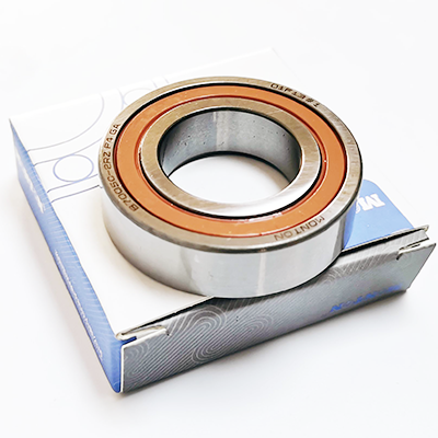
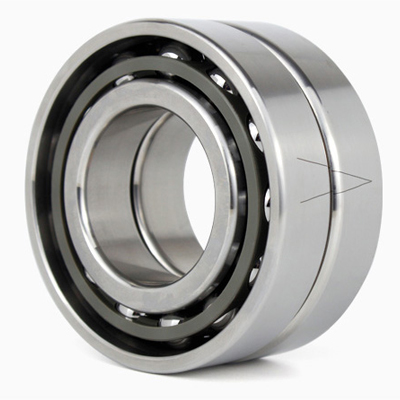
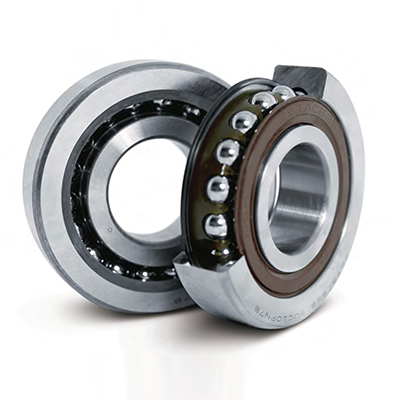
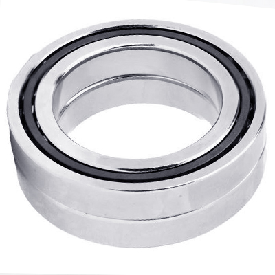
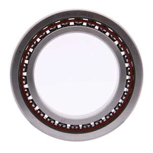
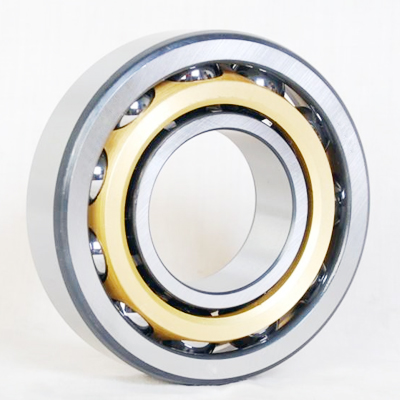
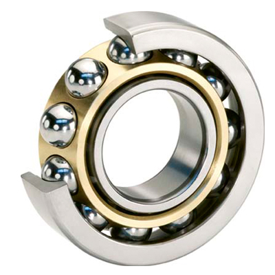
Angular contact ball bearings can not only withstand radial load and axial load in one direction, but also accommodate only axial load in single direction, radial loads produce axial forces in these bearings that need to be balanced by counter forces.Therefore, the single row angular contact ball bearings often need to be installed with other bearings which withstand axial load in the opposite direction. In other words, the angular contact ball bearings are commonly used in pair, or in groups with three, four and even five bearings. Angular contact ball bearings have higher limiting speed.

When a load is applied to an angular contact ball bearing, elastic deformation and the amount of stress at the contact point changes as a result of the varying load conditions of the balls, inner ring, and outer ring according to the contact angle of the bearing.
Loads acting on two rolling elements for 30˚ contact angle, and 15˚ contact angle.

The larger the contact angle, the smaller the load acting on the rolling element. Load at the contact point, and its consequential deformation, is reduced thus resulting in longer life. When a radial load is applied, the smaller the contact angle, the smaller the load acting on the rolling element, thus resulting in reduced load at the contact point.
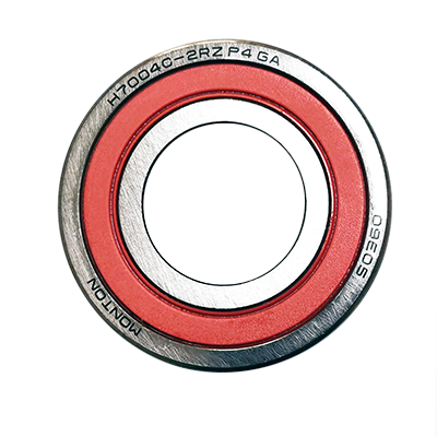
Bearing Designations

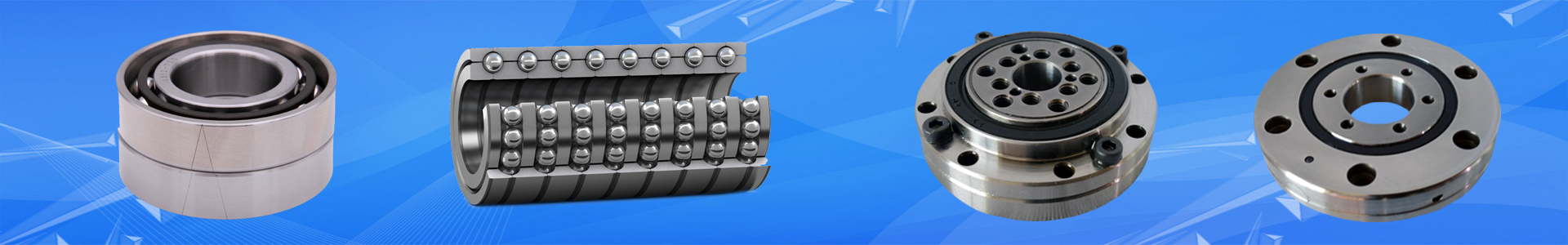
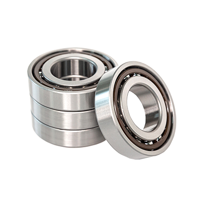
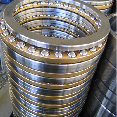
Angular Contact Ball Bearing Combinations
The combinations of angular contact ball bearings used for the fixed end of spindles are usually 2 row (DB), 3 row (DBD), and 4
row (DBB) sets. However, in 3 row combinations the preload is unevenly distributed between the bearings, resulting in a very
limited optimum range of preload which makes them unsuitable for high-speed applications.
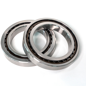
Matched bearings are manufactured as sets, so when they are mounted adjacent to each other, the specified preload is
automatically achieved. The variation of bore and outer diameter within each set of matched bearings is adjusted to less than 1/3
of the permissible tolerance.

Features
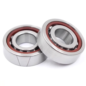
1.Back-to-back Arrangement, DB
Axial loads in both directions and radial loads can be
sustained. Since the distance between the effective load
centers is large, this type is suitable if moments are
applied. However, in case of insufficient housing accuracy
or shaft misalignment, internal load of the bearings could
be large enough to possibly cause premature failure due
to the high level of moment stiffness.
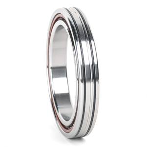
2.Face-to-face Arrangement, DF
Compared with the DB type, the distance between the
effective load centers is small, so the capacity to sustain
moments is inferior to the DB type. On the other hand,
this type is suitable for use with housings that have less
accuracy or larger shaft deflections due to low bending
stiffness of the shaft.
3.Tandem Arrangement, DT
Axial loads in one direction and combined loads can be
sustained. Since axial stiffness of this type is twice the
value of a single row type, this arrangement is used
when the axial load in one direction is heavy.
If preload is required, it needs to be applied externally,
e.g. by using a spring.
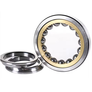
4.Three Row Arrangement, DBD
Axial loads in both directions and radial loads can be
sustained. However, the preload distribution to each
bearing is not equal, and preload on the counter side
(single side) is twice that of the other side. Consequently,
this type is unsuitable for high-speed operation because
of the large increase of internal load on the single side,
which could lead to bearing failure.
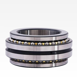
5. 4 Row Arrangement, DBB
Axial loads in both directions and radial loads can be
sustained. In situations that have the same axial clearance as DB arrangement, preload and stiffness are twice that of
the DB arrangement. Also, the permissible axial load of a 4
row arrangement is larger than that of a DB arrangement.

Mounting Instructions for Matched Angular
Contact Ball Bearings
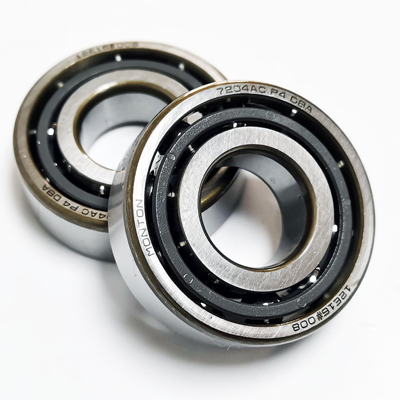
Direction of Matching
For matched bearings, the mounting order and load
application direction are very important. As shown in Fig. 3.6,
marks on the outer ring surfaces of the bearings form a “V”
when the bearings are properly matched and aligned.
Radial Run-out Mark
On the side surface or chamfered part of the inner rings, the
symbol “O” is marked to indicate the position of maximum
radial run-out. Optimum accuracy is achieved when the
bearing is mounted so the “O ” symbol is placed directly
opposite the point of maximum shaft eccentricity.
The Symbol for the Position of Maximum Radial Runout of the Inner Ring

Combinations of Angular Contact Ball Bearings

Important Points to Consider When Using Matched Bearings
The axial clearance (stand-out) of each bearing in a set of matched bearings (DB, DT, DFD etc.) has been adjusted and
controlled, so that the specified amount for each standard preload is achieved when the bearings are arranged in the order
indicated by the marks on the surface of their outer rings. These marks form a “V” when the bearings have been correctly
mounted. Thus, as long as the bearing direction and the order of the bearings are not altered, bearing axial clearance or preload
gap is controlled even if some bearings are selected from a bearing set. In this case the marks on the outer rings will also form
continuous straight lines.
Should the direction or order of matched bearings be changed, the clearance adjustment of mating surfaces will be lost and the
resulting clearance values will be unknown. If used this way, problems may arise due to excessive or insufficient preload and
uneven load distribution. Therefore, in order to use matched bearings in other than the prescribed directions and order, it is
necessary to measure the stand-out (offset) of each individual bearing and use spacers to adjust the axial clearance according to
these measurements.
We do not recommend machining the bearings themselves to the desired offset, as debris from grinding may remain inside the
bearing.
To customers who wish to use the same bearings on various machines, we recommend stocking universal combination bearings
rather than sets of matched bearings prepared for specific arrangements. Universal combination bearings are ready for use in
different arrangements.

DBB Combination

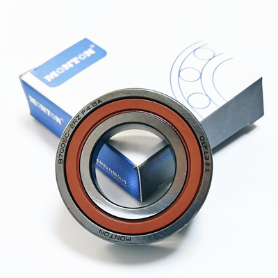
Universal Combination Bearings
MONTON manufactures universal combination bearings which have been controlled to have the same amount of stand-out (offset) on
their front and back faces. That way, for bearings with the same bearing number, users will achieve the specified amount for each
standard preload, regardless of which combination they chose. Each universal combination bearing comes with a V-shaped mark
on the surface of the outer ring to simplify identification of the correct direction when mounting and to ensure that the correct
combination is achieved. The V-shaped mark points to the direction of the axial load that the inner ring supports (contact angle).

Tolerances of P4 and P4Y Accuracy DU Combination

Combination Mark and Matching Method for Universal Combination Bearings
Arrangements of Universal Combination Bearings

Comparison MONTON bearings with other brand bearings

Bearing Tolerance
Bearing “tolerances” or dimensional accuracy and running accuracy are regulated by ISO 492:2002 standards (rolling bearing tolerances) .
When mounting a bearing to a shaft or housing, the dimensional accuracy is crucial in satisfying the
tolerance. A permissible run-out occurring when rotating a bearing by one revolution is defined by the running
accuracy. Appendix III shows bearing accuracy for angular contact ball bearings, BS series bearings, and
cylindrical roller bearings. Methods for measuring the accuracy of rolling bearings are described inGB/T307.1-2015.
Bearing types and applicable tolerance and comparison of tolerance classifications of national standards

For other technical parameters, please contact with us!