

 English
 Russian
 Chinese


Four Point contact ball bearing
|
|

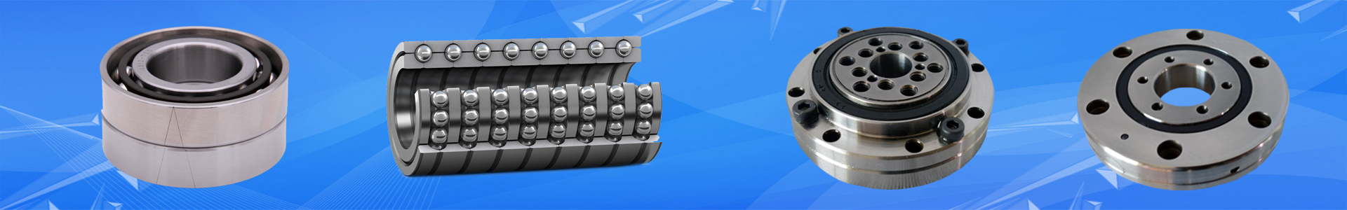
A four-point contact ball bearing can accommodate axial loads in both directions, in combination with radial loads up to a certain level, and provides a very tight axial shaft position tolerance. The bearing also saves space, because it can be seen as the combination of two single row angular contact ball bearings into one. Therefore, it is an excellent choice in applications such as industrial gearboxes, locomotive drives and compressors.
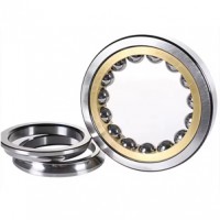
Four-point contact ball bearings – also called QJ bearings – consist of a single piece outer ring, a radially split inner ring, a ball set and an outer ring guided cage. The ring designs show some remarkable details . The outer ring is similar to a deep groove ball bearing design, but the raceway geometry cross section is fairly different. A deep groove ball bearing raceway is circular. A four-point contact ball bearing outer ring consists of two symmetrical raceways. Each of them has a circular shape. The two raceways intersect each other in the middle of the ring in form of a singular point. The raceways form is also called “Gothic arc”. The centres of the two raceway circles have a small off-set in axial direction. The inner ring is split into two halves and has the same design principle as the outer ring. This provides an advantage compared to the deep groove ball bearing design. The design of the outer ring raceways allows defining the contact angle (standard 35°) and the axial clearance independently. In other words it is possible to design a specific axial clearance without changing the osculation (ratio between raceway curvature and ball diameter).
A bearing with a 35° contact angle requires high raceway shoulders and such a bearing with a single piece
inner ring cannot be assembled with a reasonable number of balls. The four-point contact ball bearing split
inner ring design makes it possible to incorporate a maximum number of balls, only limited by the cage bar
thickness.
Typically, there is a three-step assembly procedure:
1.the cage is inserted in the outer ring,
2.the balls are pressed into the cage,
3.the inner ring halves are inserted from each side. The inner rings are not self-retaining. To avoid the bearing
falling apart during transport and handling, a plastic insert is pushed into the bore.
Four-point contact ball bearings as standard are fitted either with a machined window-type brass cage (designation suffix MA)or an injection moulded window-type cage of polyether-etherketone (PEEK) (designation suffix PHAS) . Both cages are outer ring guided. This gives a very good guidance, enabling to increase the speed limit. The very specific design of the symmetric cage enables to incorporate a maximum number of large balls.
Applications:
1.Screw compressors
2.Turbo retarders
3.Multiphase pumps
4.Wind turbine gearboxes
5.Railway


